Unit 2 Summary Blog Post
In this unit, we learned all about forces and their interactions, free body diagrams, and Newton’s 1st and 3rd Laws. We began with the basics, which was an overview of each force including how and where they act, and how they work on a free body diagram. We learned about Newton and his laws, even doing a few experiments to prove their dependency until we got more advanced and could apply them to all types of general life situations such as how seatbelts keep one safe in a car, and how the motion of a skydiver is affected by a parachute. We learned how to calculate weight as well as friction, and definitely, the biggest challenge of all was applying numbers to our free body diagrams to calculate other values from the number using SOH CAH TOA.
BFPM.1:
Wherever we go and whatever we do, there are always forces interacting around us. In BFPM.1, we learned how to recognize those forces and make a diagram for the system called a Free Body Diagram.
FORCE OVERVIEW:
F of Gravity: stems from the Earth and is an attraction between and object and a planet towards the center of the planet- it always points down from the surface
F of Friction: occurs as a result of 2 objects rubbing together- it always points in the opposite direction of motion parallel to the surface
F of Tension: occurs along a rope or string when it is taut (pulled in general direction)- it is always in the direction being pulled
F of Normal: occurs when two surfaces touch each other that prevent one another from using the same space- occurs perpendicular to the surface
F of Air: occurs when the force of air is pushing against an object- occurs opposite to the direction of motion
Free Body Diagrams:
By definition, a free body diagram, or a force diagram, is a graphical illustration used to visualize the applied forces, movements, and resulting reactions on a system. We’ve done various types of free body diagrams this unit ranging from basic to advanced, yet they all encompass the same general premises. Basically, a free body diagram represents the forces being done TO THE OBJECT/SYSTEM, not the force the object itself is doing, which is a general misconception and an easy way to mess up the diagram.
Constructing a BASIC Free Body Diagram with Horizontal Coordinate Axes:
When making a free body diagram, you want to start with a dot in the center of the intersecting X and Y axes. This dot represents, the system (it could be a log, wagon, etc.), and it is the object you will focus on when figuring out what forces are applied on it. The X axis, drawn horizontally, represents a flat surface and the Y axis represents the direction perpendicular to the surface The arrows, also called vectors, can be used to represent the direction the forces are applied, and the size- the longer arrows are the largest, and the shorter ones the smallest. When the vectors are congruent on both sides (either horizontally or vertically), it means the forces are equal/balanced so the object is either at rest or traveling at a constant velocity. When one vector is longer than the other, it means the object has an unbalanced force causing it to slow down, speed up, or change direction.

The diagram above represents a simple free body diagram with normal, friction, applied, and weight (gravity) forces on a system. The X axis represents the flat surface with the normal force pointing upwards, perpendicular to the surface, and the force of gravity is shown pointing downwards from the surface. Horizontally, the friction force is drawn to the left, meaning the object’s direction of movement is to the right, and the F applied force, meaning it could be a pull, push, or any other force that could be applied, is drawn to the right in the direction of motion. Notice all the vectors are equal/congruent, so the object is either traveling at a constant velocity, or not moving at all.
Findng the Equation of Forces in the Horizontal and Vertical Directions:
The equation of forces is basically a statement of what all the forces combined, either along the horizontal or vertical axes (you never combine forces that aren't on the same axes), equal when added together. In the diagram above, the equation for forces in the vertical direction (Y axis), would be F Normal+F Gravity= 0N, and for the horizontal direction the equation would be F Friction and F Applied = 0N. Because the vectors are balanced in both the horizontal and vertical directions, we know that the two forces counteracting each other equal 0 because they cancel each other out. Pretend the F Applied force is drawn longer that the F Friction force displaying that the object is moving to the right, then the equation would be F Friction + F Applied > 0N because the forces aren't canceling out causing movement.
BFPM.2:
Newton’s 1st Law- an object in motion stays in motion, and an object at rest stays at rest until acted upon by an unbalanced force Example: ball in motion will continue to move at the same constant velocity unless an unbalanced force speeds it up, slows it down, or changes its direction ball at rest will stay at rest unless a force moves it
Our study on this law first began when we rode hovercrafts in the gym. Using the law we were able to figure out why we stayed in motion once someone pushed us off, and why we would have stayed in motion unless someone stopped us. While traveling, there were no forces keeping us in motion, therefore the forces were balanced which is why were traveled at a constant velocity and would have kept traveling at a constant velocity until an unbalanced force was applied. An unbalanced force causes an object to slow down, speed up, or change direction, and in this case, the unbalanced force that caused us to stop, was a person waiting at the other end with their hands out. They applied the unbalanced force greater than the force of motion which stopped us, and then applied another unbalanced force to push us back in the opposite direction.

The diagram above represents Newtons’s 1st Law. The car at the top represents an object at rest that will stay at rest unless acted upon by an unbalanced force, and the car at the bottom represents the object in motion that will stay in motion unless acted on by an unbalanced force.
Newton’s 1st Law and Seatbelts:
Seatbelts keep us safe in a car, because when traveling, you are moving at the same speed as the car. When an accident occurs, a force is applied to the car to make it slow down, but that same force is not applied to you, meaning you will continue to move at the same speed the car had been traveling which is what can cause you to fly through the wind shield. The seat belt prevents this from happening because it applies an unbalanced force (in the horizontal direction) that stops your motion and prevents you from flying forward.
Unbalanced Forces and Skydivers:
The speed of a parachutist changes throughout his journey from the plane to the ground and it is because of the effect of unbalanced forces. For this particular example you would only focus on the forces in the vertical direction, as the horizontal forces are non-applicable at this point because he is falling downwards. When he first jumps out of the plane, he is speeding up because the direction of the unbalanced force, also the only force acting on the skydiver at the moment which is gravity, is in the same direction of movement. Terminal velocity, or constant velocity, is reached when the forces in the vertical direction are balanced, so the force of air and the force of gravity are both equal. The skydiver would start to slow down when the force of air, stemming from his pulled parachute is greater than that of the force of gravity, and since the unbalanced force is pointing upwards, or in the opposite direction of motion, he will slow down.
KEY FACTS to REMEMBER:
- when the unbalanced force is in the opposite direction of motion the object will speed up
- when the unbalanced force is in the direction of the motion, the object will speed up
- when the forces are balanced/equal/congruent the object is traveling at a constant velocity or it’s not moving at all
BFPM.3:
Calculating Weight:
When calculating weight, you use the formula w=(g)(m). The w, is the weight in Newtons, the g is the universal gravitational constant which is set at 9.8, but for our purposes we’ve been allowed to round it to 10N/kg, and the m is the mass in kilograms, and it represents the number of atoms or how much matter is present in an object. For example, when trying to calculate the weight of an object that is 750 kg, you would do the following: (750)(10)= 7500N. When trying to find the mass of an object that is 500N you would do the following: 500= (10)(x), divide 500 by 10, and get x which equals 50 kg.
BFPM.4:
Friction: as stated earlier, friction always opposes the direction of motion, and is often the underlying cause of many phenomena that we see on our every day lives. As will be described later on, friction is the reason one team wins a game of tug of war, the reason why a buggy can pull a cart, and many more. It is also stated that surface friction is equal to the normal force of two objects pressing together.
Calculating Friction:
When calculating the friction of an object you simply plug values into the formula: F= (Mk)(weight). F is the friction found in Newtons, Mk is the coefficient of friction, and weight is the weight in Newtons.
AFFECTS AIR RESISTANCE: speed and surface area
AFFECCTS FRICTION: nature of surface and weight
DOES NOT AFFECT FRICTION: speed or surface area
what affects are resistance does not affect friction
The coefficient of friction is a constant based on the surface of the 2 interacting objects
BPFM.5:
Constructing a Free Body Diagram with Shifted Coordinate Axes:
The process for constructing a free body diagram with shifted or tilted coordinate axes is the exact same as making one with horizontal axes except you must be aware of which direction you tilt the X and Y axes so they properly match the picture and you can accurately apply the forces. It is important to remember that the X axis is the surface, so it must be angled in the same direction as the diagram. The reason for shifting the diagram is for visualization purposes: if we are meant to diagram a car driving up a hill or a skier coming down a slope, it is easier to tilt the axes in the direction the system is traveling or located.
you would shift the axes if the example looks similar to the following:
notice the skier coming down the slope at an angle- therefore this diagram would require a tilted axis. For this example, the x axis, which represents the surface, is going to run from the top left to the bottom right in the same direction as the “slope” or hypotenuse of the triangle is displayed. For better viewing purposes the axes would look like the following:
here the box is moving down an incline but in a different direction, therefore a tilted axis is also required but the X axis would be tilted in the opposite direction than the example above, pay careful attention to the difference because inaccurately naming the axes could cause major problems down the road. It should look like the following:

Components
Components come into play on a free body diagram when vectors are at angles that do not match up with the direction of the axes, whether they be horizontal or tilted. For example, on a tilted axis, the force of gravity has to point downwards, naturally meaning the vector does not align with the shifted diagram, so you must split up the gravity vector into X and Y components that combine to make the single downward pouting vector. Basically, a vector can be seen as having two parts that when combined, make one. We did an example in class where Maren and Ms. Lawrence both pushed a table in different directions, and it moved in a direction that was like a “middle way” between their two pushes. The diagram below shows a visual representation of how components of a single vector work.
BPFM.6:
Newton’s 3rd Law: for every action, there is an equal and opposite reaction
Example: ground pushes dog up, dog pushes ground down
girl pulls wagon, wagon pulls girl
How a Team Wins Tug of War:
The common misconception is that the team who pulls the hardest will win a game of tug of war, but that is actually incorrect. Because of Newton’s 3rd Law, we know that both teams pull each other with equal force because they are action-reaction pairs: team a pulls team b while team b pulls team a, so the determining factor for which team will win is how much friction is between their feet and the ground.
How a Buggy Pulls a Car (Horse and Cart Problem):
Extremely similar to the tug of war example, we completed a horse and buggy challenge problem in class. Relating to Newton’s 3rd Law, the cart pulling the horse and the horse pulling the cart are action reaction pairs, therefore they are equal and opposite, so unlike common assumption of horse pulling the cart with a “greater force” is not the cause for the movement of the cart. Once again, the cause for the cart’s movement is because of friction. As the cart begins to move, the friction on the horse’s hooves becomes greater than the friction on the cart’s wheels which causes it to move. The diagram below displays the forces that are present on both the horse and the cart.

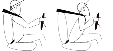
Examples of Newton’s 3rd Law Free Body Diagrams:
The diagrams above represent two examples that represent Newton’s 3rd Law. The example on the left is an accurate display of an action reaction pair because the earth pushes the body down, while the body pushes the earth up. The example on the left shows that the body pushes down on the table while the table pushes up on the body, also an action reaction pair.
KEY TIPS TO REMEMBER WHEN USING NEWTONS’S 3RD LAW:
- remember to draw vectors equal and opposite when making free body diagrams
- forces can be equal and opposite without being an action-reaction pair. For example, this is not an example of an action-reaction pair: earth pulls book down, table pushes book up. This, however, is an example of an action reaction pair: book pushes table down and table pushes book up
a force is one half of the interaction between 2 objects
SOLVING BALANCED FORCE PROBLEMS USING SOH CAH TOA
Sometimes it is necessary to solve for certain components of a free body diagram using angles, so this is where trigonometry comes into play. Often times a diagram will provide an angle measurement and the weight or force of tension for one of the vectors. You then have to use the information given to solve for a given component using SOH CAH TOA.

The example above is from a lab we completed towards the end of the unit. We were given the values for the forces of tension (notice the components), and we were told to solve for gravity, the unknown value. Because this object is not in motion, we know that the forces must be balanced on each side, so we can infer that the two Y (vertical) components of friction are each half of the total force of gravity, or weight of the object. We were also given two angle measurements: 23 and 75 degrees. Using the laws of geometry, we know that each quadrant is equal to 90 degrees, making it easy to find the other angle measurements of that quadrant. Then considering what values you have been given, you use either Sine, Cosine, or Tangent to solve for FT1y and FT2y. Because you have the adjacent and hypotenuse, you can use the Cosine of angles 65 and 15. You then simply plug the values into the equation and solve for each vector. After solving you add the values together and that is equal to the weight or gravity of the object. The work is shown in the picture.
Application: I found this unit to be extremely applicable to daily life. Whether we realize it or not, there are always forces acting on each other that create some sort of effect, and learning about how they work greatly changed my perspective. It was super interesting for me to learn that a team wins tug of war not because of how hard they pull, but because of friction, a theory that is extremely counterintuitive. I also found Newton’s Laws to be extremely relevant because they disprove common misconceptions about the way we view interactions between forces.